Geometry Node Screen-Space Invert Hull Outlines
UPDATE
With Blender 3.6, there’re improvements to drivers, which makes this system a lot easier to setup and work with. The update can be found here, and is better written.
Table of Contents
Preface
In stylized realtime rendering, one way to achieve outlines is the Invert Hull method; the mesh is duplicated, each vertex offset along the normal, and is rendered via a back-face-only material with a solid color. You can see this employed by Arc System Works in their 3D anime fighting games such as the recent installments of the Guilty Gear series.
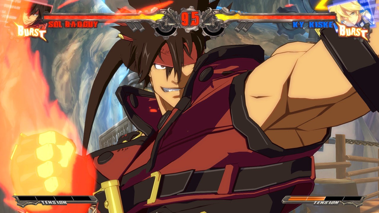
Look closely on the outlines, and you can see how it follows the polygons. This is especially evident on Sol's left deltoids.
Simple Invert Hull in Blender
In Blender, the easiest way to achieve this is to use the Solidify modifier with flipped normals and a material that only renders the back-face.
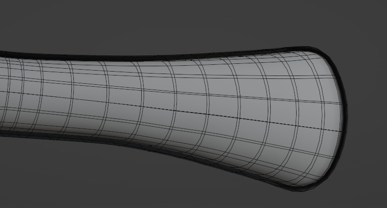
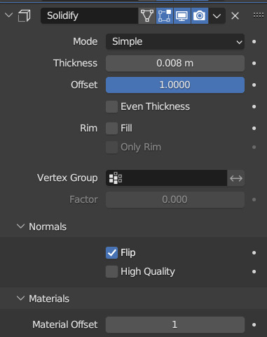
The mesh has an outer shell, which is the invert hull outline. Notice that we have Material Offset set to 1, meaning the solidified mesh will use the second material slot assigned to the mesh, which is a black emissive material that only renders its back-face.
However, this has limitations:
- The modifier can only act on one mesh at a time, making managing this on a multi-mesh character, or an entire scene, difficult without building additional tooling.
- The modifier has a uniform value for how far to extrude the outline mesh. Meaning the outline thickness is defined in world space.
- This can be attenuated with vertex weights, but modifying vertex weights in real time is bit of a pain in Blender, and we can only use values between 0-1
- At extreme angles, world space outline thickness makes the closer part of the mesh appear to have a thicker outline than the rest of the mesh.
- Though depending on art direction, this could be desirable.
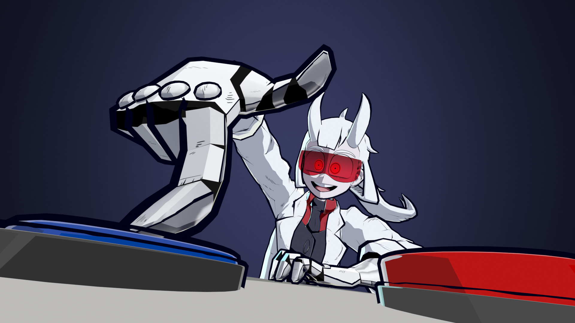
The hand's outline is significantly thicker than the objects behind it, and the outlines on the button are clipping as well
So how do we do this?
In order to achieve a more consistent and uniform invert hull result, we must redefine its thickness in screen space. Normally in a game engine, this is easy to do: you’d implement invert hull in geometry shaders, with the vertex shader passing in the screen-space/clip space matrix for you to then perform invert hull calculations.
Unfortunately in Blender, we do not have access to the vertex or geometry shader, nor do we have access to any matrices outside of Python scripts. So here’s where Geometry Nodes come in.
Geometry Node Based Invert Hull
With Geometry Nodes, rather than only being able to extrude the invert hull cage along its vertex normal, we can specify exactly how we want it to move. With some simple vector math, we can achieve a result that gets you a much more uniform invert hull thickness within screen space. This means that the outlines stays consistent regardless of your camera’s rotation and location; allowing you to set and forget then carry on with the rest of your animation. Plus, we can organize the nodes such that every outline can be controlled from one (or arbitrary many) places.
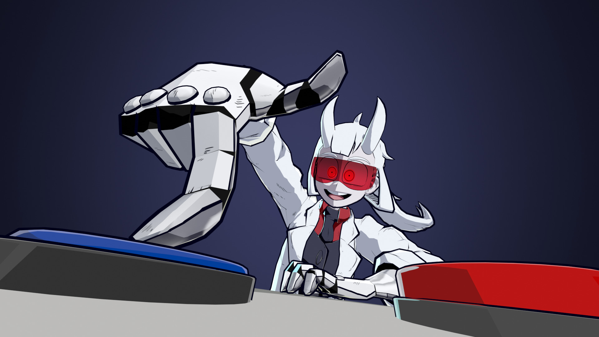
Now the entire model's outline is much more uniform, with the buttons looking much better too
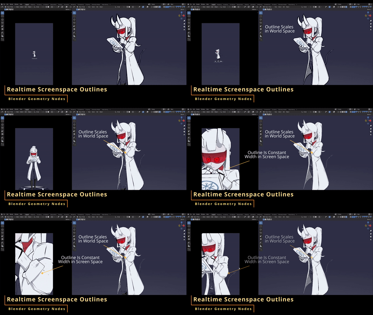
Realtime Demo
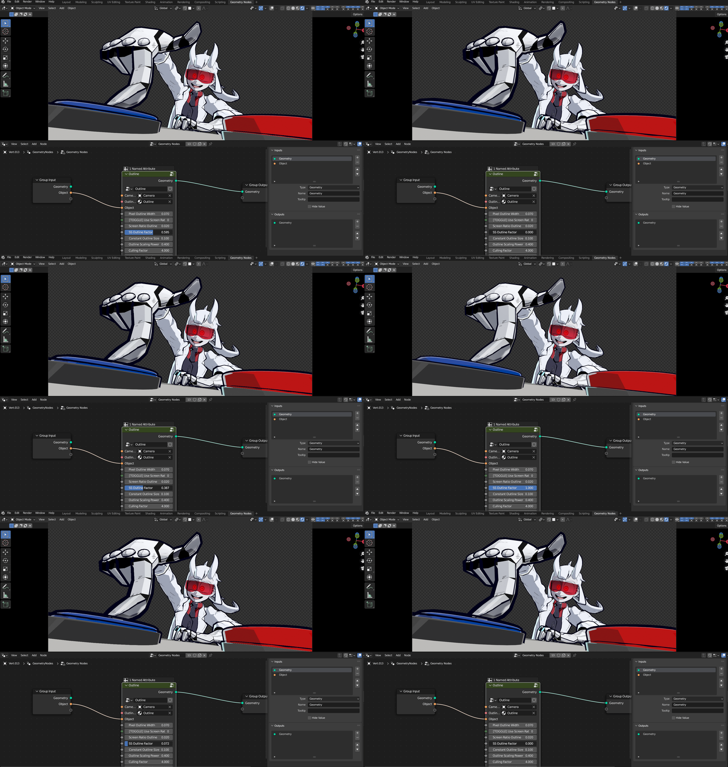
The outline of every mesh can be controled by changing the property of a single Geometry Node graph
The basic principle
So the idea is to take our vertex normal vector, project it such that it is parallel to the near-plane/far-palne of the camera, then scale it by a factor that is will be the length that we want it to be in screen space, and finally projecting it back to the original normal vector while preserving its screen space length.
So that was a mouthful of words, which probably wasn’t too helpful to many people. So here’s a more visual demonstration, where the arrows represent the normals.
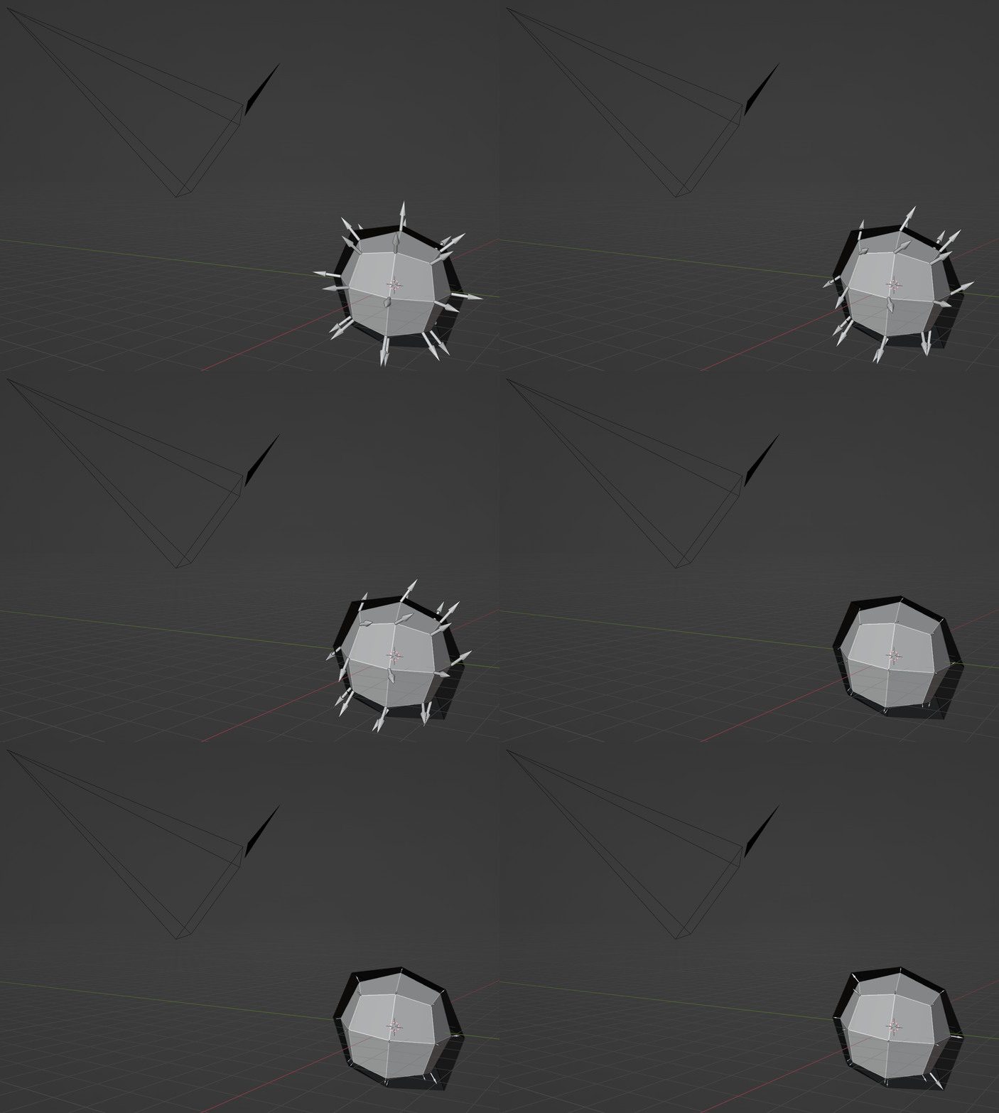
- The first transform is projecting the normals to be parallel to the camera’s near/far plane.
- Then we scale the vectors such that they’re the same size in screen space.
- We re-project the vectors back onto the original normal vectors while maintaining their screen space size. This is to avoid artifacts from the shell clipping with the original model.
From the camera’s point of view, the last step doesn’t look like the vectors have changed direction or length at all, which is what we want.
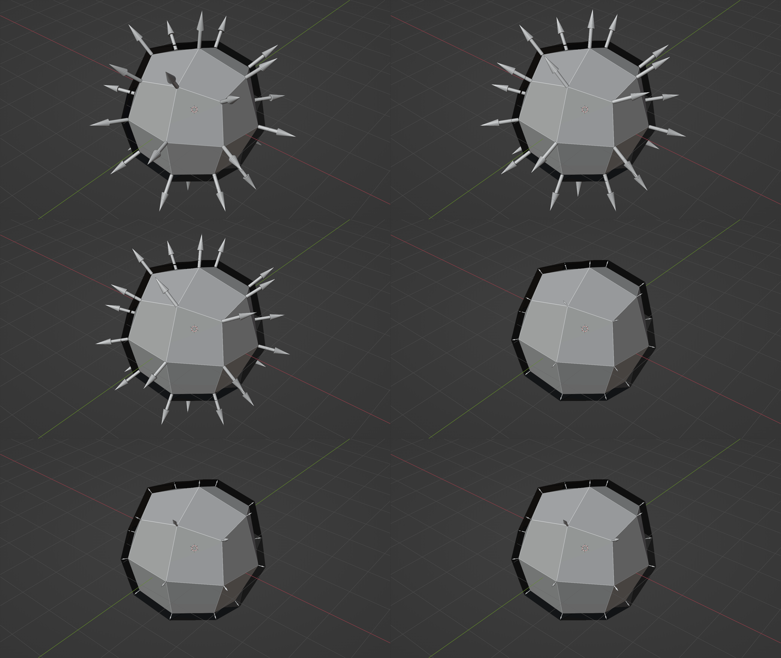
The vector arrows still changes slightly due to them moving towards/away from the perspective camera in 3D space still
Implementation Time!
1. Project Normals to Camera Plane
The node graph looks like this
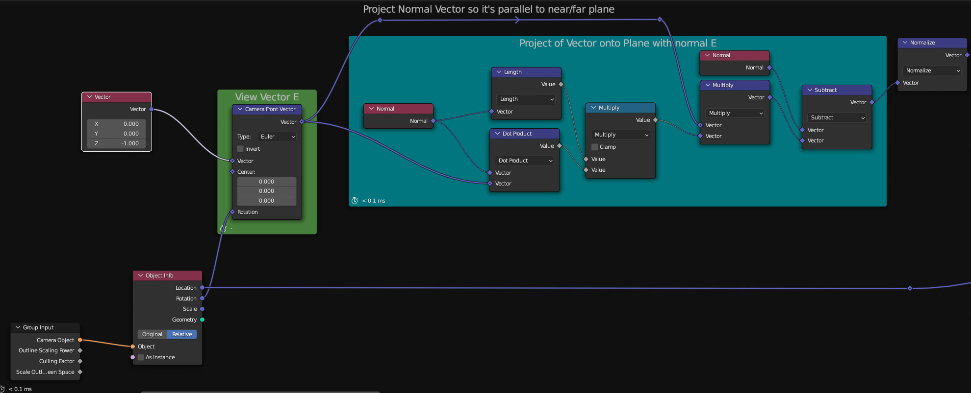
Calculate Camera view vector from (0,0,-1); the default camera orientation, then project normals to camera plane.
2. Scale Projected Normal Vectors in Screen Space
2a. First we calculate the world space length of X pixels in screen space at each vertex. Specifying pixel count works, but when render resolution changes so does the outline size, so I added a screen-space ratio option to preserve outline sizes regardless of the resolution.
![]()
2b. To make the Outlines dynamically respond to changing camera parameters, we pass in the focal length and dimensions through drivers.
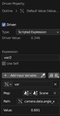
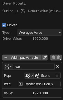
2c. Attenuate and multiply with step 1
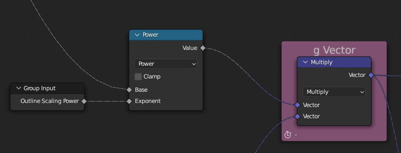
3. Re-project back to Normal Vector
3a.
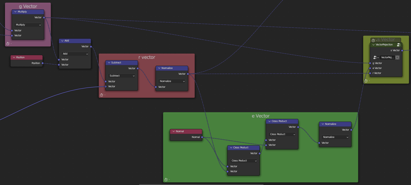
Check out this PDF for an explanation on projecting a vector onto a plane from any angle
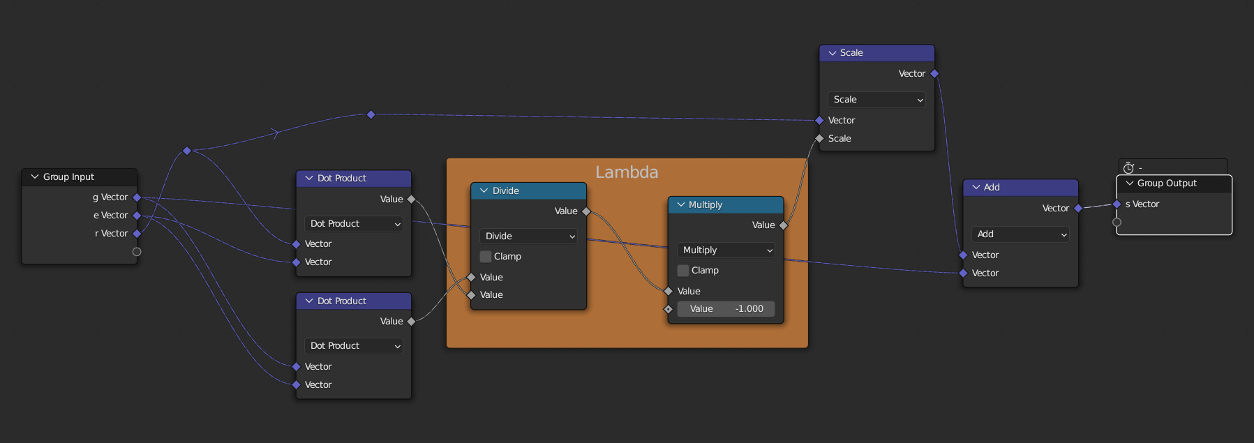
Inside of the VectorProjection vector group
4. Putting it all together
4a. We may see weird artifacts when the normal vector is close to being parallel to the vector from the camera to the vertex, because the normal vector needs to be scaled more after step 2 to be parallel to the original normal vector. So we must attenuate these vectors. We can do so via the absolute value of the dot product.
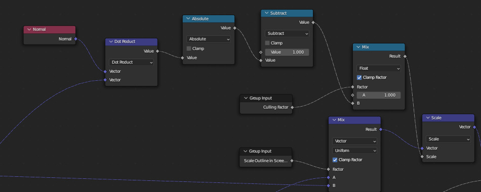
Mix node's input A and Dot Product's input B is the g Vector, and B is the s Vector from 3
4b. We want to provide options for using and world space constant outlines and blending between that and screen space outlines, so we add the following nodes.
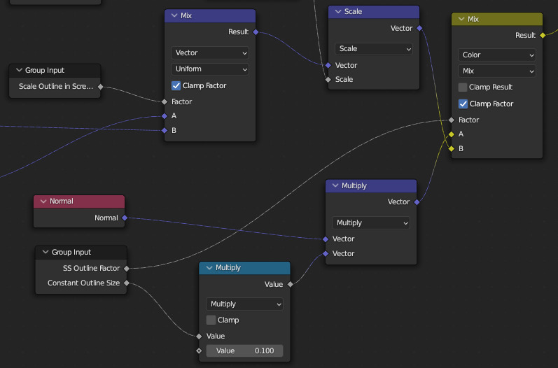 4c. We make use of vertex weights to allow further user attenuation of the outlines. Also, the re-projection may cause some vectors to point inside of the mesh instead of out, do we perform a dot product check and invert the vectors. This still preserves the screen space size of our outlines.
 4d. Extruding our invert hull then just involves giving each vertex the offset that we calculated, flipping its normals, and setting an outline material.

Done!
And done! Now you have a geometry node that takes a geometry, camera, and material, and outputs invert hull outlines in screen space, with a variety of adjustment options. If you want to control multiple mesh objects with this, nest it inside 2 layers of nodes, and use the top layer as the geometry node object for the modifier.